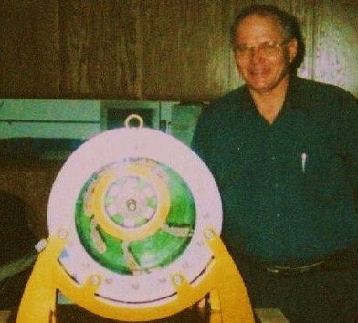
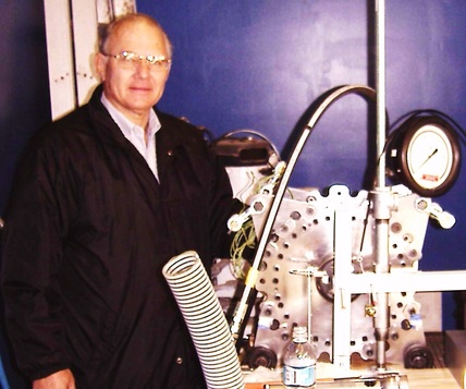
Mert Pekrul with the FE-1 Swing Vane Engine Mert Pekrul Testing the FE-2 Sliding Vane Engine
(Working Model, August, 2005) (Compressed-Air used for Bench Tests, Jan, 2006)
|
|
Re-Examining Old Technologies A Fresh Approach to Solving the Historic Problems
|
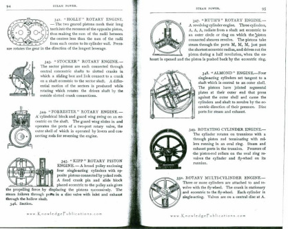
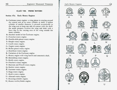
Sample Pages copied from Herbert Herkimer,
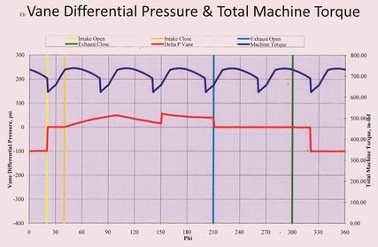
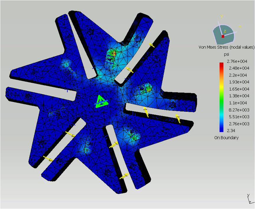
Engineers’ Illustrated Thesaurus, Penn Publishing/Chemical Publishing, pp. 368-371: Early Rotary Prime Mover Engines pp. 332-339: Early-Type Rotary Pumps Observation: You see Rotary Pumps & Rotary Compressors today, but there are no truly efficient Rotary Expander Engines. Why? They have not typically functioned well enough to be taken seriously. It has almost always comes down to overcoming an inherent problem of the Rankine heat cycle. Current attempts to resolve this problem has resulted in the development of new working fluids, known as Organic Rankine Cycle (ORC) refrigerants. These new fluids will typically go to vapor phase at about 90F. These fluids are now being used in equipment powering electrical generators . Again, this is a step in the right direction. The FE can use this specialized fluid (closed-loop), or water (steam, open-loop). One way to characterize the historic problem: not having sufficient temperature differential between the inlet and exhaust ports to sustain good vapor flow, without wasting fuel. Historically, the rotary devices have either been too hot, or too cold. If too hot, then fuel is wasted. If too cold inside the engine, then condensation occurs, and engine parts break. The other classic problem with any type of rotary engine or rotary pump device is the leakage of vapor either over-the-top of the end plates, or the vane tips, or vane body. If that does not occur, then typically the friction issues are so high that efficiencies are very low, or parts wear out quickly. There are now some major companies who are making claims as to the efficiencies of their root-type expanders, but “efficiency” is not considered a real issue because of the use of geothermal heat energy. Their claims include a "uniqueness" to the manner of cutting the interlocking 'teeth', and trapping the vapor in a manner which minimizes leakage. This is a step in the right direction, but still seriously flawed. Fibonacci Motors has taken a unique and ‘Fresh Approach’ to solving the historical Problems. Result: Technological Break-Throughs have Resulted in Significantly Increased Rotor Dynamic Efficiencies. Large sums of monies are being spent today on the development of inherently flawed systems. Finally, the historic, fatal design flaws have now been solved with the Fibonacci Energy System (FE). Third-party Field testing of the FE-4 Engine is needed to properly validate this claim. The Field tests will be conducted as soon as possible. Conclusions Drawn from Test Results of the Fibonacci Compressed-Air / Rotary Steam Engine (FE-2) in 2006 What can the Fibonacci Engine do better than any other Engine, for its Weight to Horse Power Ratio? *Produce High Torque Power *at Low RPM *at Lower Costs *Minimal Pollutants Graph: Vane Differential Pressure & Total Machine Torque Preliminary Test Results from FE-2, used for Extrapolation of Performance for the FE-3 The extrapolated Test Results for the FE-3 have resulted in the design of the FE-4 (not shown). The FE-4 incorporates the improved design modifications gleened from the Bench Tests of the FE-2 (the FE-2 is shown in the Videos). The FE-4 requires further computer simulation models using Comsol Multi-Physics software. Then will follow fabrication, Bench Testing, and Prototype Field Testing. Fully documented third-party validation of the Efficiency Reports will then be made available. Having said that, the Bench Tests on the Fe-2 were done objectively and accurately, and the computer program which was used, was considered accurate within + 5%. The simulation program was regularly checked against actual test results, resulting in further 'fine-tuning' of the program. Several hundred sets of Bench tests were run. After a dozen or more Bench Tests were run in a given set, the FE-2 was torn down, examined, and re-assembled, with new internal modifications each time. This approach provided the Inventor the means to make internal design changes in the vanes and seal system, and to immediately determine if the newly-made change(s) did in fact improve the performance of the engine. The FE-2 was prcisely designed as a "Test Engine", and incorporates design variations of the FE-2, FE-3, FE-4, and FE-5. Note: The Engine in the Videos is the FE-2. The same Bench tests were then run again, revealing whether the new internal design changes improved or downgraded the previous test runs. This process went on for several months. The data gathered provided the basis for making many modifications in the seal system, for example. These changes continued to decrease the leakage yet lower the friction. The classic problems of rotary vane engines such as,"Over- the-Top" , or end plate leakage, rotor vane slot leakage, vane tip chattering, vane dampening, etc, were all addressed. Additional time was taken as required between test runs in order to digest the test data. Then the data was translated into the the actual design improvements embodied in the engine designated as the FE-4. |
Examples of Historic, Early
|